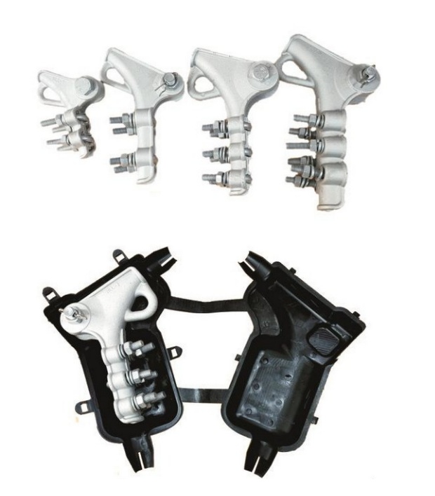
| Product | Bolt Type Tension Clamp NLL Series |
|---|
| Category | Tension & Dead-End Clamps |
|---|
| Representative range / models | NLL-1–NLL-4; conductor diameter 8–24 mm including wrapping tape |
|---|
| Standards / reference basis | Bolt model specifications; project requirements confirmed by KOVYEL |
|---|
| Typical applications | Conductor anchoring at terminal poles; Angle-pole tension insulator assemblies; Distribution line and substation conductor terminations |
|---|
| Series | NLL-1 to NLL-4, bolt type |
|---|
| Material | Aluminium alloy |
|---|
| Application | Overhead distribution applications up to 10 kV, with insulation arrangement confirmed for the project |
|---|
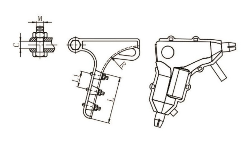
| NLL-1 | Conductor diameter 8.0–12.0 mm; L 90 mm; L1 40 mm; R 85 mm; M 16 mm; C 18 mm; 2 U-bolts; rated breaking load 40 kN |
|---|
| NLL-2 | Conductor diameter 11.0–16.0 mm; L 100 mm; L1 40 mm; R 115 mm; M 16 mm; C 18 mm; 2 U-bolts; rated breaking load 60 kN |
|---|
| NLL-3 | Conductor diameter 15.0–20.0 mm; L 155 mm; L1 45 mm; R 150 mm; M 16 mm; C 27 mm; 3 U-bolts; rated breaking load 70 kN |
|---|
| NLL-4 | Conductor diameter 19.0–24.0 mm; L 170 mm; L1 50 mm; R 175 mm; M 18 mm; C 30 mm; 3 U-bolts; rated breaking load 90 kN |
|---|
| Diameter basis | The stated conductor diameter includes aluminium wrapping tape. |
|---|
| Dimension symbols | L, L1, R, M and C correspond to the dimensional drawing; dimensions are in mm. |
|---|
| Load terminology | Rated breaking load is not allowable working load. Mechanical selection must follow the project design. |
|---|
| Insulating cover | Optional matched cover; inclusion and insulation requirements must be confirmed with KOVYEL. |
|---|
| Final dimensions and ratings | Confirmed against the approved drawing, equipment interface and project specification |
|---|
| Supply basis | Project-specific RFQ, coordinated documentation and export packing |
|---|