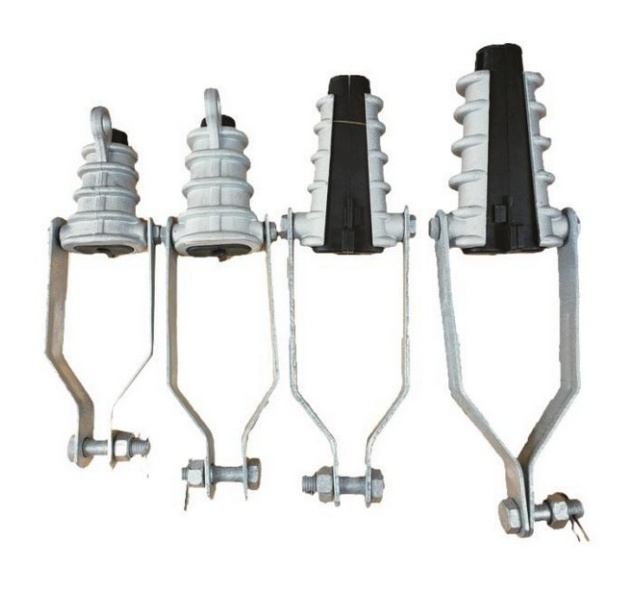
| Product | NXJG Insulated Wedge Tension Clamps – Clevis Type |
|---|
| Category | Tension & Dead-End Clamps |
|---|
| Representative range / models | NXJG-1–NXJG-4; JKLYJ-10 conductor, 35–240 mm² |
|---|
| Standards / reference basis | NXJG model specifications; project requirements confirmed by KOVYEL |
|---|
| Typical applications | Insulated overhead conductor anchoring at terminal structures; Conductor retention at the ends of tension sections; Clevis-connected tension insulator assemblies |
|---|
| Series | NXJG-1 to NXJG-4, clevis type |
|---|
| Conductor designation | JKLYJ-10; model values below apply to the 10 kV conductor designation |
|---|
| Material | Aluminium-alloy body with insulating wedge |
|---|
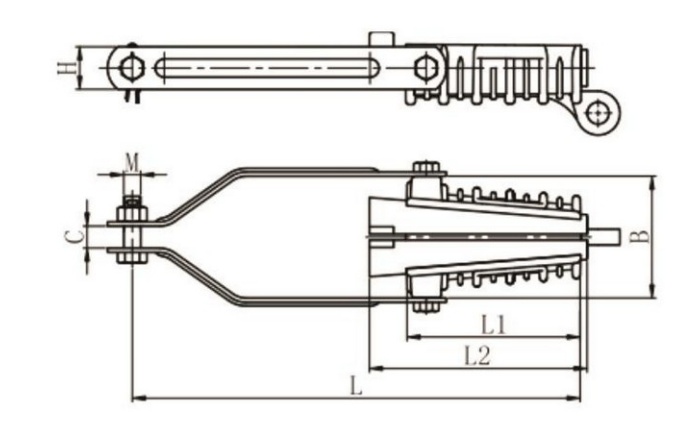
| NXJG-1 | Conductor 35–50 mm²; L 230 mm; L1 90 mm; L2 120 mm; B 70 mm; H 25 mm; C 18 mm; M 14 mm; rated breaking load 7.4 kN |
|---|
| NXJG-2 | Conductor 70–95 mm²; L 272 mm; L1 105 mm; L2 140 mm; B 76 mm; H 28 mm; C 18 mm; M 16 mm; rated breaking load 14.5 kN |
|---|
| NXJG-3 | Conductor 120–150 mm²; L 322 mm; L1 125 mm; L2 165 mm; B 90 mm; H 30 mm; C 18 mm; M 16 mm; rated breaking load 22.1 kN |
|---|
| NXJG-4 | Conductor 185–240 mm²; L 370 mm; L1 145 mm; L2 185 mm; B 100 mm; H 35 mm; C 18 mm; M 16 mm; rated breaking load 36.4 kN |
|---|
| Installation | No insulation stripping; select an insulating wedge suitable for the actual conductor. |
|---|
| Dimension symbols | L, L1, L2, B, H, C and M follow the dimensional drawing; all dimensions are in mm. |
|---|
| Load terminology | Rated breaking load is not allowable working load; confirm the project mechanical design. |
|---|
| Selection boundary | Specifications are specific to NXJG; other voltage or model configurations require separate confirmation. |
|---|
| Final dimensions and ratings | Confirmed against the approved drawing, equipment interface and project specification |
|---|
| Supply basis | Project-specific RFQ, coordinated documentation and export packing |
|---|